Colour Coding:
The electric and electronic circuits of all types employ various types of electronic components namely, active elements- junction diodes, transistors, field effect transistors e.tc. and passive components- Resistances, capacitors, inductors e.tc. The resistances used in electronic circuits, particularly of higher value are the carbon resistances. The values of these carbon resistances are coded the colours of the rings present on their bodies.

The carbon resistances usually have four rings of different colours A B C and D on their bodies as shown in Fig.1 The first three rings A, B and C are equally spaced from the left hand side of the reader and the fourth ring D is widely spaced as compared to the other rings.
The first two rings A and B indicate the first two digits or significant figures in the value of resistance of a conductor in ohms. The third ring C shows the decimal multiplier 10x as x = 0,1,2,3,4,5,6,7,8,9 in accordance with Colour code. The fourth ring D indicates the tolerance as per table given below.

For example: In fig. 1 given above in case first two rings A and B are of green and red colour, the third ring C is of brown colour while the fourth ring D is of silver colour. According to the colour coding table given above, the value of the given resistance will be: R = 52 x 101ohm +/- 10% = 520 ohm +/- 10%
In fig. 1 given above in second case two rings A and B are of blue and green colour, the third ring C is of red colour while the fourth ring D is of golden colour. According to the colour coding table given above, the value of the given resistance will be: R = 65x 102 +/- 20% = 6500 ohm +/- 20%
Laws of Combination of Resistances:
In electronic circuits, the resistors of different values are used in order to get the required amount of electric current to flow in an electric component in the circuit and develops proper biases and voltages. Thus, in order to get a resistor of the proper and required value, we combine several resistance in different ways. These different ways of combining of a number of resistances are called the laws combination of resistances
Law of Series combination of Resistances:
The network of a number of resistances in an electric circuit is called a series combination when the electric current passing trough each resistance is same but potential difference across each one is different.

Let us suppose that three resistors R1, R2, and R3 are connected in series to a battery of e.m.f. V volt. An electric current I passes though each resistor and V1, V2, & V3 be the potential difference developed across each resistor, the applying ohm’s law we can write, V = IRs , V1 = IR1 , V2 = IR2, and V3 = IR3 —1. Since, the sum of the potential differences developed across each resistor is equal to the emf of battery. Thus, we can write V = V1 + V2 + V3 —2 Putting eqn. 1 in eqn. 2 we get IRs= IR1 + IR2 + IR3 Also, IRs= I(R1 + R2 + R3)
Rs= R1 + IR2 + IR3 —3 Thus, the equivalent resistance of a series combination is equal to the algebraic sum of the resistances of all the individual resistors.
Key points:
- The electric current flows through all resistors equally.
- The total electric resistance of a network is equal to the sum of the resistances of all the individual resistors and the internal resistance of the cell, if any.
- T he potential difference across the resistors is different and is proportional to their individual resistances as I is same.
- The relative positions of the various resistors in the electric circuit does not affect the magnitude of the current in the circuit but it will be same.
- The resistors are connected in series to increase the resistance of the network because the equivalent resistance in this type of combination of resistors is always greater than the largest one in combination.
Law of Parallel combination of Resistances:
When the two or more resistors are connected such that the potential differences across each one are same and equal to the applied emf of the battery and the electric currents through each one are different and their sum equals the current passing through the circuit
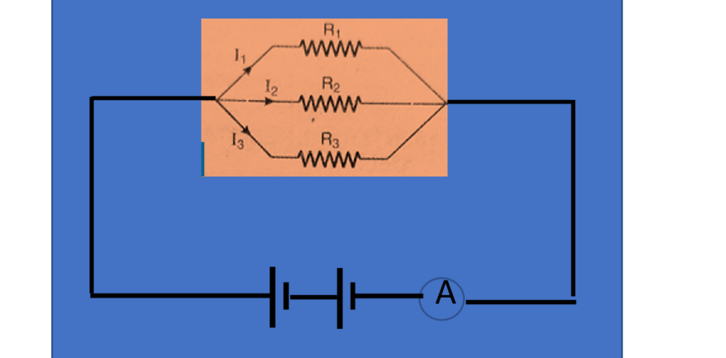
Let us suppose that the three resistors R1, R2 and R3 are connected to a battery of emf V volt in parallel such that I1, I2 and I3 be the electric currents passing through these resistors and V is the potential difference across them which is equal to the emf of the battery. From the circuit diagram, we can write as follows I = I1 + I2 +I3 —4 using ohm’s law, V = I1 R1 = I2 R2 = I3 R3 we can write, I1 = V/ R1, I2 = V/ R2, I3 = V/ R3,
Putting these values of currents in eq. 4, we get
I = V/ R1 +V/ R2 + V/ R3 —5 Now using V = I Rp, I= V/Rp —6 comparing Eqn. 5 and 6, we get V/Rp = V/ R1 +V/ R2 + V/ R3
1/Rp = 1 / R1 +1 / R2 + 1 / R3 —7 Thus, when a number of resistors are connected in parallel, then the reciprocal of the equivalent resistance of this combination is equal to the sum of the reciprocals of the resistance of individual resistors.
Key Points:
- The potential difference developed across each resistor in a parallel combination is equal.
- The electric current through any resistor varies inversely to its resistance.
- The reciprocal of the equivalent resistance of the parallel combination is equal to the sum of the reciprocals of the resistances of the individual resistors.
- The sum of the currents through all the resistors in a parallel combination is equal to the total current in the circuit.
- The equivalent resistance of an electric network in parallel mode is always less than the smallest resistance and thus, this combination is used to decrease the resistance of the circuit.
A carbon resistance has the colour pattern of rings as given in the below fig. Find the value of the resistance ?
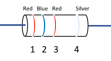
Ring 1 Red and Ring 2 Blue give = 26 and Ring 3gives= 102 Thus the total resistance will be =26 x 102 ohm + /- 10%
A carbon resistance has the colour pattern of rings as given in the below fig. Find the value of the resistance ?
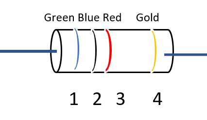
Ring 1= Green and Ring 2 Blue = 56, Ring 3 Red = 102 Ring 4 = 5% Thus, Value of Resistance will be R = 56 x 102 +/- 5% ohm


