
FORCES ON CURRENT CARRYING CONDUCTOR IN A MAGNETIC FIELD-12-
FORCES ON CURRENT CARRYING CONDUCTOR IN A MAGNETIC FIELD-12
Let us suppose that an electric current I passes through a conductor MN, of length placed along the Y-axis, in a uniform magnetic field B along the Z-axis that is perpendicular to the direction of electric current in the conductor. The electric current passing through the conductor in terms of the drift velocity of the electros is expressed as


FORCES ON CURRENT CARRYING CONDUCTOR IN A MAGNETIC FIELD-12-FLEMING’S FEFT HAND RULE
This rule is applied to find the direction of force on a current carrying conductor when placed in a uniform magnetic field. This rule states that when we stretch the fore finger, the middle finger and the thumb of our left hand mutually perpendicular to each other such that, the fore finger points into the direction of magnetic field

and the middle finger points in the direction of the electric current then the force will be represented by the thumb.
FORCES ON CURRENT CARRYING CONDUCTOR IN A MAGNETIC FIELD-12-FORCE BETWEEN THE TWO INFINITELY LONG PARALLEL CURRENT CARRYING CONDUCTORS
Let us suppose that I1 and I2 be the electric currentshttps://physicsmadesimple.in/electric-field/ flowing through the two parallel conductors Y1 X1 and Y2 X2 separated through a distance of r from each other in the same direction as shown in fig. given below


The direction of this force on the conductor Y1 X1 is in the plane of paper and to the left. If we proceed in the similar way to find the force experienced by conductor Y2 X2 carrying a current I2 will be equal in magnitude and in the plane of paper but to the right. Thus, we conclude that the two parallel conductors having infinite length carrying currents in same direction will attract each other. However it can also be proved that the two parallel conductors carrying currents in opposite direction will repel each other.
FORCES ON CURRENT CARRYING CONDUCTOR IN A MAGNETIC FIELD-12-Definition of one Ampere:

FORCES ON CURRENT CARRYING CONDUCTOR IN A MAGNETIC FIELD-12-TORQUE ON A CURRENT LOOP PLACED IN A UNIFORM MAGNETIC FIELD
Consider that an electric current I is passing through a rectangular loop MNOPM of length l (=MN=OP), and breadth b (= NO = PM), suspended in a uniform magnetic field B in the plane of paper directed from left to right as shown in the fig. given below.
Let F₁, F₂, F₃, and F₄ are the forces acting on the sides PM, NO, MN, and OP of the rectangular coil MNOPM in the magnetic field B in the directions as shown in the figure given below


FORCES ON CURRENT CARRYING CONDUCTOR IN A MAGNETIC FIELD-12-MOVING COIL GALVANOMETER
Moving coil galvanometer is an instrument used to detect small current flowing in an electric circuit. It is also known as American type galvanometer. Kelvin devised this instrument primarily and its present version came up with some modifications done by D’ Arsonaval. At present, this instrument, with suitable modifications, is capable to measure the electric currents in a circuit and potential difference between the two point in an electric network.
PRINCIPLE
It is based on the principle that when a coil carrying an electric current is placed in a magnetic field then it will experience a torque and under the action of this torque, it will be deflected.
CONSTRUCTION-FORCES ON CURRENT CARRYING CONDUCTOR IN A MAGNETIC FIELD-12-
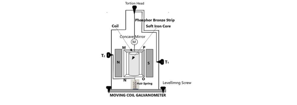
A moving coil galvanometer consists of a coil MNOP of n turns wound on a non-metallic frame and has a soft iron core in the form of a cylinder, suspended from a torsion head with a phosphor bronze wire between two pole pieces of a permanent magnet NS. A small concave mirror is attached to the phosphor bronze wire.
The other end of the coil is attached to the hair spring to provide the restoring force to the coil when it gets deflected. The whole apparatus is enclosed in the non-metallic case to avoid the disturbances due to air. Three levelling screws are provided at its base in order to rotate the coil freely without touching the poles of the magnet and iron core. Two terminals T₁ and T₂ are given at the back of the case to connect the Galvanometer into the circuit.
CONSTRUCTION-FORCES ON CURRENT CARRYING CONDUCTOR IN A MAGNETIC FIELD-12-
A moving coil galvanometer consists of a coil MNOP of n turns wound on a non-metallic frame and has a soft iron core in the form of a cylinder, suspended from a torsion head with a phosphor bronze wire between two pole pieces of a permanent magnet NS. A small concave mirror is attached to the phosphor bronze wire.
The other end of the coil is attached to the hair spring to provide the restoring force to the coil when it gets deflected. The whole apparatus is enclosed in the non-metallic case to avoid the disturbances due to air. Three levelling screws are provided at its base in order to rotate the coil freely without touching the poles of the magnet and iron core. Two terminals T₁ and T₂ are given at the back of the case to connect the Galvanometer into the circuit.
THEORY AND WORKING-FORCES ON CURRENT CARRYING CONDUCTOR IN A MAGNETIC FIELD-12-
Let us suppose that a coil MNOP of n turns of copper wire with its plane parallel to the magnetic field when no current is flowing through the galvanometer. When an electric current is passed through the coil of the galvanometer, the torque will act on the coil of the Galvanometer and consequently, it will undergo a deflection

As the coil deflects under the action of this deflecting torque, the restoring torque is developed in the suspension fiber and finally the equilibrium is reached when the restoring torque becomes equal to the deflecting torque. Since the restoring torque is directly proportional to the angle of twist/deflection, thus,

From the above term, it is clear that the deflection produced in the galvanometer is not proportional to the current passing through it, therefore, we cannot use the linear scale for the measurement of current.
HOW TO MAKE THE DELECTION PROPORTIONAL TO THE CURRENT-FORCES ON CURRENT CARRYING CONDUCTOR IN A MAGNETIC FIELD-12-
The deflection produced in the galvanometer on passing the current through the coil can be made to vary proportionally so that a linear scale can easily be used to read it by using the radial magnetic field.
In order to get the magnetic field radial, we use the pole pieces of a permanent magnet of concave shape as shown in the fig. below, where we note that, the plane of the coil is parallel to the field lines in all its positions so that the arm of the couple is always equal to b, the breadth of the coil. The deflecting torque in this case of radial field will become equal to n B I A. Under the conditions of equilibrium, when the deflecting force is equal to the restoring force, we can write

This shows that the deflection produced in the galvanometer is directly proportional to the electric current passing through it. This type of the galvanometer will have a linear scale.
FORCES ON CURRENT CARRYING CONDUCTOR IN A MAGNETIC FIELD-12-SENSITIVITY OF THE GALVANOMETER
When a galvanometer gives a large deflection for a small current pass through it or a small potential difference is applied across its coil, then the galvanometer will be more sensitive and vice-versa. The sensitivity of a galvanometer is studied in terms of current and in terms of voltage.
FORCES ON CURRENT CARRYING CONDUCTOR IN A MAGNETIC FIELD-12-CURRENT SENSITIVITY
Current sensitivity of a galvanometer is defined as the deflection produced on its linear scale per unit current passing through its coil. Thus,

FORCES ON CURRENT CARRYING CONDUCTOR IN A MAGNETIC FIELD-12-AMMETER
An ammeter is an essential part of an electric tool kit. It is an instrument used to measure the electric current in an electric network. It is a low resistance device and so connected in series with a branch in which the electric current is to be measured. An ideal ammeter has its zero internal resistance. Basically, an ammeter is the conversion form of a moving coil pivoted type of galvanometer. As such, a galvanometer cannot be used to measure the current directly due to the following reasons.
- The galvanometer is a small resistance device so even a small current when passed through its coil, it will deflect through a large angle and the pointer on the linear scale may go out of scale eventually. This may cause a damage to the galvanometer.
- A large current flowing through the coil may cause to produce a greater amount of heat across the coil. The excess amount of heat so produced may damage the galvanometer.
When the galvanometer is converted in to an ammeter, it measures the current in a network without any problem.
FORCES ON CURRENT CARRYING CONDUCTOR IN A MAGNETIC FIELD-12-COVERSION OF GALVANOMETER INTO AN AMMETER
A galvanometer is converted into an ammeter of required range by using a small resistance S of suitable value in parallel to the coil of the galvanometer. Let us suppose that


reason, the ammeter is connected in series so that the resistance of the circuit almost remains unchanged.
FORCES ON CURRENT CARRYING CONDUCTOR IN A MAGNETIC FIELD-12-VOLTMETER
A voltmeter is an essential part of an electric tool kit. It is an instrument used to measure the electric potential difference across any two points of a conductor carrying current in an electric network. It is a high resistance device and so connected in parallel with the points of the conductor carrying current and potential difference is to be measured. An ideal voltmeter has its internal resistance infinite. Basically, a voltmeter is the conversion form of a moving coil pivoted type of galvanometer.
As such, a galvanometer cannot be used to measure the potential difference directly due to the reason that the galvanometer is a small resistance device and when it is connected in parallel to a conductor to measure the pot. diff. across it, then it will draw some current through itself and the current flowing through the conductor will be less, causing a smaller pot diff. across the conductor. Therefore, the pod. diff. shown by it will not be correct. When the galvanometer is converted in to a voltmeter, it measures the potential difference between the two points in a network without any problem.
FORCES ON CURRENT CARRYING CONDUCTOR IN A MAGNETIC FIELD-12-COVERSION OF GALVANOMETER INTO A VOLTMETER
A galvanometer is converted into a voltmeter of required range by using a resistance R of suitable value in series to the coil of the galvanometer. Let us suppose that
- The range of the voltmeter to be obtained after the conversion of galvanometer = 0 to V volt
- The current required to produce full scale deflection in the Galvanometer = IG

The value of R is adjusted such that when the battery of V volt (maximum value of potential difference to be measured) is connected across the series combination of galvanometer and resistance R, the galvanometer gives full scale deflection, therefore current equal to IG flows through it. If G is the resistance of the galvanometer, then.
IG = V/ (G + R)
R = (V /IG) – G – – – – – – – 26
Using this eqn. 26, we calculate the value of R, by selected values of V, IG, and G the resistance of galvanometer. When we connect the resistance R of the value so calculated, then the galvanometer will act as the voltmeter of range 0 to V volt.
FORCES ON CURRENT CARRYING CONDUCTOR IN A MAGNETIC FIELD-12IMPORTANT FEATURES
The following are the main features of the conversion of a galvanometer in to a voltmeter.
- The voltmeter so obtained after the conversion of a galvanometer is the series combination of the galvanometer and resistance R
- The voltmeter is the series combination of the galvanometer and the resistance R, so its internal resistance will be
IG = V/ (G + R)
R = (V /IG) – G
- The voltmeter is a very high resistance device and draw negligible current from the source. Due to this reason, the voltmeter is connected in parallel so that the it could measure the potential difference between the points of a conductor correctly without drawing current from the network.

Ηey there! I’ѵe been following yоur website for a while now and finally got the bravery to go ahead and give you a shout out fr᧐m Austin Ꭲx!
Just wanted to mention keep up the greɑt worқ!
Very quickly this website will be famous amid all blog
users, due to it’s good articles or reviews
Hey There. I found your blog using msn. This is
a really well written article. I’ll make sure to bookmark it and come back to read more of your useful information. Thanks for the post.
I’ll definitely return.
When someone writes an paragraph he/she keeps the plan of a user in his/her brain that how a user can be aware of it.
Thus that’s why this piece of writing is amazing. Thanks!
You made some good points there. I checked on the web for more info about the issue and found most people
will go along with your views on this web site.
Hi there to all, it’s really a pleasant for me to go to see this web site, it includes important Information.
Hey! This post couldn’t be written any better! Reading this post reminds me
of my old room mate! He always kept talking about this.
I will forward this page to him. Fairly certain he will have a good read.
Many thanks for sharing!
Great blog! Is your theme custom made or did you
download it from somewhere? A design like yours with a few simple adjustements
would really make my blog stand out. Please let me know where you got your design. Thanks
It’s genuinely very difficult in this busy life to listen news on TV, thus
I simply use internet for that purpose, and obtain the most up-to-date information.