communication
People used to use trained pigeons to deliver messages back in the day. This method of the Principles of communication was unreliable, though. A messenger by the name of Harkara used to go through different towns so that the general populace could interact with one another. People could either give messages to him or receive them from him after they had been sent through their friends and family.
You can understand why a messenger would need a lot of time and effort to travel the distance between the two locations. As a result, this approach also turned out to be rather impractical. The messenger was given a horse as a treatment so that he could travel between two locations relatively quickly.
By giving the messenger a horse, communication became considerably simpler and quicker. In actuality, this strategy only partially solved the issue of carrying messages from one office to another. However, it created the framework for contemporary communication techniques. Since the invention of electronics, messages have been transmitted using electric signals that are placed on high-frequency carrier waves (instead of a person riding a horse), and the recipient can decipher the message using various electronic devices.
This means of communication is known as radio communication. A lot of different communication systems have been developed as a result of the recent enormous technological advancements. The brief history of publishing’s development over time is provided in the paragraphs that follow.
| Sr. No. | Period | Mode of principles of Communication | Remarks |
| 1 | Early days | The use of trained pigeons and drum-beating | Through trained pigeons to distant places Through drum beating to close places |
| 2 | The era of 13th to 16th century | Messages through messengers | Qutab-ud-din Aybak used the dak-system, and in 1296, Allaudin Khilji expanded into dak-chowkis, a horse and foot runner service. |
| 3 | During 19th century | 1. Postal Services 2. Telegraph: 3. The telephone was invented by Alexander Graham Bell 4. Wireless telegraphy, invented by J. C. Bose and Marconi | *Austria in 1869 and USA in 1873 introduced the world’s first postcard *The first telegraphic message was transmitted on May 24, 1844, reading, “What has God wrought?” *In 1875, the first sound speech was transmitted. *Marconi sent messages through wireless telegraphy in 1895. |
| 4 | During 20th Century | 1. Television, invented by J. L. Baird. 2. FAX- invented by Alexander Bain. 3. ARPA Net- invented by Licklider 4. Fiber Optics-by Bell Labs. 5. World Wide Web-invented by Tim Berners-Lee | *BBC in 1936, made first television transmission. *Alexander Bain, sent first FAX transmission on March 4, 1955. *JCR Licklider in 1962, connected the computer users through internet in similar way as it is today. *Fiber optics telephone system, information network and data communication started in 1977. *The idea of global information medium as world wide web to the computer users was started in 1990 |
We now have quick and effective means of communicating messages, thanks to the innovations listed above. For instance, using the phone allows us to call anyone on the globe and speak with them. Televisions provide both auditory and visual information on events taking place all around the world. In the past, people who lived far apart might speak with one another by congregating at a meeting site. It entails lengthy travel, which is a major time waste. However, these meetings may be held without the need for travel thanks to video phones and satellite conferencing. The sphere of communication has undergone a complete revolution thanks to fax machines, e-mail, etc.
IMPORTANT TERMS IN COMMUNICATION SYSTEMS
The following terms are frequently used in electronic communication systems:
1. Transducer:
A transducer is an electronic tool that transforms one form of energy into another.
Many different types of transducers exist. Electricity is transmitted through a transducer in electronic communication systems. An electrical transducer is a device that transforms changes in a physical variable, such as pressure, force, temperature, or replacement, into matching changes in electrical impulses.
2. Signal:
The term “signal” refers to a time-varying electrical signal produced from the original signal utilizing a transducer in an electronic communication system. The data from the source is included in it. Distinct sources produce distinct signals that vary in magnitude, frequency, or nature.
The signals are of the following two types:
(a) Analog signal:
The amplitude of a signal continually changes with time in an analog signal. The signal’s amplitude at any given time serves as a representation of the signal’s value at that time. By utilizing the right transducer, such signals can be readily produced from the actual waveform of the information. With the aid of a microphone, for instance, pressure differences in sound waves can be translated into matching current or voltage variations. A photocell can similarly be used to translate changes in a light signal’s intensity into changes in current and voltage.
The sound of a tuning fork is a pure note, or the sound of a single frequency. It also offers an analog signal in its most basic form, whose amplitude fluctuates sinusoidally with time, as shown in Fig. 1.01. The equation (01) given below represents the instantaneous value of such a signal.
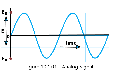
E =E0 Sin ωt (01)
Where f =ω/2ꙥ gives the frequency of the signal and E0, the maximum amplitude of the signal.
(b) a digital signal.
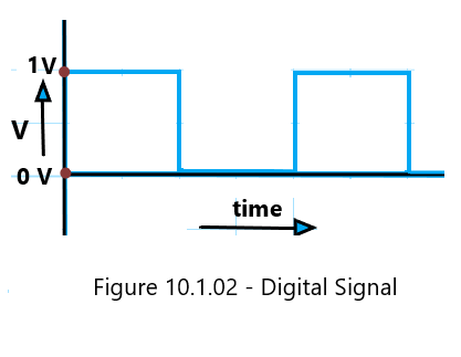
The signal’s amplitude is discontinuous in time in a digital transmission. There are only two possible values for the amplitude of a digital signal: low (zero) or high (some fixed number). A digital signal therefore takes the form of pulses that are typically evenly spaced apart in time. Typically, binary coding is used to encode the two levels of a digital signal. As illustrated in Figure 1.02, the binary digit 0 represents a signal (let’s say voltage) when it is low, and the binary digit 1 indicates a signal when it is high.
3. Modulation:
Low-frequency signals lack the energy necessary for long-distance transmission. It is overlaid on a high-frequency wave (known as the carrier wave) in such a way that some characteristics of the carrier wave change in line with the signal in order for it to go to a distant location.
Modulation is the process of combining the signal and the carrier wave. A modulated signal is the result of combining the original signal with the aid of an assisted frequency wave.
4. Transmitter:
A device that converts the signal into an electric signal, mixes it with a carrier wave, and then transmits it into the medium is called a transmitter.
5. Noise:
Noise is typically caused due to atmospheric electricity, changes in industrial electric power, etc. Unwanted signals accompany the original signal as a result of noise.
6. Range:
The range of the signal is the furthest distance that the destination can be from the signal’s source while still receiving a strong enough signal.
7. Attenuation:
The loss in the strength of the signal as it propagates through the medium is called attenuation.
8. Amplification:
The signal’s intensity diminishes during transmission. As a result, the signal may not be strong enough when it arrives at the destination to be accurately duplicated. Using an electronic circuit known as an amplifier, the signals must be amplified in order to make up for their loss in strength. Amplification is the process of boosting the signal’s strength through the use of an amplifier.
9. Demodulation:
The process of demodulation (or detection) is the inverse of modulation. Therefore, the process of separating out the original signal (intelligence) from the modulated signal is known as demodulation.
10. Receiver:
A device that extracts the original signal from the modulated signal is known as the receiver.
11. Repeater:
Repeaters are placed along the path of the signal when the distance between the transmitter and the destination is very great or when mountains, for example, block the sent signal. The signal is captured, amplified, and then transmitted once again to the receiver. In order to increase the communication system’s range, a repeater is a receiver and transmitter set up along the signal’s journey.
ANTENNA:
The antenna is a key component of a communication system. Radiofrequency signals are transmitted and received using it. The pick-up antenna transforms electromagnetic waves back into electrical energy, while the transmitting antenna transforms electrical energy into electromagnetic waves.
There are many different types of antennae in the realm of communication, and each type has a particular set of uses. The characteristics of an antenna, such as the frequency of the carrier waves and the signal’s directivity, among others, affect how it is built. Two popular antenna types include the following:
A dipole antenna:
It has an important role in telecommunication, and it may send or receive radio signals in all directions. It is essentially a straight conductor [1.03]. The antenna’s length should be chosen so that, at the operating frequency, it functions as a resonant circuit.
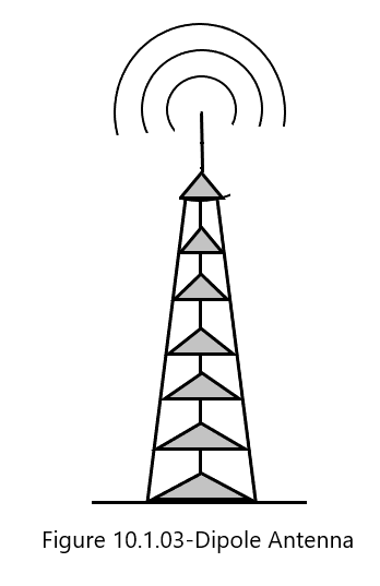
The length of a Hertz antenna is half the wavelength (λ/2) of the radio signal that is being sent or received. It can be placed either horizontally or vertically. The transmitting antenna produces vertically polarized waves when it is positioned vertically and horizontally polarized waves when it is positioned horizontally.
The length of a Marconi antenna is equal to one-fourth of the radio signal’s wavelength (pi/4). It is set up vertically, with the bottom of the object touching the ground. The voltage and current distributions set up in the antenna are reflected off of the ground. Close to the earth, it gets fed. An antenna-ground system emits electromagnetic waves that are identical to those produced due to a Hertz antenna.
The antenna’s length works out to be in the range of 5,000 m for an audio signal frequency of 15 kHz. A vertical antenna of this magnitude is virtually impossible to set up. However, the length of the necessary antenna may only be a few meters for a high-frequency broadcast (about 3 MHz).
Power radiated by an antenna:
According to the research on antennas, the power emitted using a linear antenna of length L is proportional to the square of the length-to-signal-wavelength ratio (L/2)2, where L is the signal wavelength. As a result, the power radiated rises as the signal wavelength falls. Since a signal must be transmitted with high power for effective transmission, it must have a short wavelength or a higher frequency. The requirement for high-frequency transmission is thus underscored using the antenna’s length and the power it radiates.
Dish Antenna:
This type of antenna is useful in digital telecommunication in a particular direction. Such an antenna is shaped like a dish or a parabolic reflector. As seen in Figure [10.1.04], a dipole—also known as the horn feed—is positioned at the focal point of the parabolic reflector or spherical dish.
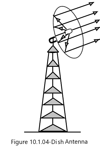
It has the ability to send signals in a certain direction and receive signals that are pointed in that direction. The signal is sent to the dipole for transmission, and the dipole then directs the signal to the reflector. The signal is then sent from the reflector as a parallel beam. The antenna is pointed in the direction of the transmissions in order to receive them. The signals are gathered at the reflector and then directed toward the dipole. The signals are sent from the dipole to the receiver’s input.
These types of antennas are used in digital communication in radar systems and for receiving broadcasts directly from communication satellites. In addition, cable operators also make use of dish antennas for receiving signals from a communication satellite.
Elements of communication system
Communication is the exchange of information between two people who are physically separated from one another, and a communication system is the tool used to do this.
In principle, a communication system consists of the following three parts:
Transmitter
Communication Channel
Receiver
Consider that two people are having a direct conversation with one another in order to comprehend the three components of a communication system. Then, the speaker may be referred to as the transmitter and the listener as the receiver, with the air in between serving as the communication channel for the sound waves.
An optical, electronic, or electrical communication system can exist. The requirements of the actual circumstances dictate the precise sort of communication system to be employed. For instance, two people can communicate with each other via the phone, whether they reside in the same city, two separate cities, or two other countries.
Here, the speaker’s mouthpiece, which is essentially a microphone on the phone, serves as the transmitter, the listener’s eyepiece, which is essentially a loudspeaker on the phone, serves as the receiver, and the telephone lines that connect the two phones serve as the communication channel. It should be noted that the message from the speaker is not transferred via the communication channel in its original form while using a telephone as a mode of communication.
The microphone of the telephone at the speaker’s end converts the original message in the form of speech into electrical pulses, which are then transmitted over the communication channel.
The original message is transformed into a format known as a message signal so that it can be transmitted through the communication channel.
The input transducer is the telephone’s microphone, located at the speaker’s end. The message signal cannot be heard as such when it reaches the receiver’s end of the telephone. The telephone’s loudspeaker at the receiver’s end converts the message signal back into the original signal. The telephone’s loudspeaker at the receiver’s end is referred to as the output transducer, and the original signal that was successfully recovered is known as the output signal.

Figure 10.1.05 shows the schematic layout of a communication system.
Let’s now comprehend the fundamental workings of a communication system that enables two people to speak to one another when they are separated through enough space that direct wire or cable connections between the transmitter and receiver are not possible. It should be obvious that in such a communication system, sending a message signal from transmitter to receiver in space without the need for cables is impossible. To do this, the message signal is transmitted from the transmitter to the receiver via radio waves.
With the use of a microphone, the information from the source is transformed into electrical pulses known as audio signals. An audio signal has a frequency range of 20 Hz to 20 K Hz and is connected with very little energy. It will quickly disappear if it is transmitted into space in this manner. The audio signal is superposed with high-frequency radio waves known as carrier waves so that it can reach up to several thousand kilometers.
The resultant signal is referred to as a modulated signal, and this process is known as modulation. Using a suitable amplifier, the signal’s power is further increased before being broadcast into space with the help of a transmitting antenna. As a result, the transmitter functions as a transducer, modulator, amplifier, and transmitting antenna in this manner of communication. The communication channel is the empty space that the modulated signal passes through.
The pick-up antenna detects the modulated signal after it has arrived at the receiver. A demodulator is then used to extract the radio signal from it. The signal loses strength because it travels a great distance to reach the receiver. An amplifier is consequently used to increase the audio signal. The audio stream is then transformed into the original information using a loudspeaker. The two people can thus interact with one another without connecting the transmitter and receiver with cables by combining the audio signal with the radio waves. As a result, a system like this is referred to as a radio communication system or wireless communication system. Figure 10.1.06 schematically depicts a radio communication system’s layout.
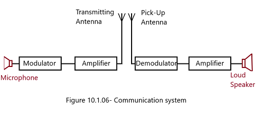
It should be noted that interference and frequency overlapping occur at the receiver when multiple audio signals are transmitted simultaneously through different transmitters. By allocating slots in a radio frequency range for the carrier waves, it is prevented. When there is no confusion or overlap, the receiver may tune into the intended transmitter.
Key points
*Communication is defined as the exchange of information between the two of more persons.
*The energy of the signal, while transmitted through an optical fiber is reduced as per the relation: I = I0 e-α where, I is the intensity of the signal wave after travelling a distance x and I0 is the initial intensity. The constant, alpha is called attenuation constant or absorption constant measured as per kilometer.
*The power of a signal through an optical fiber after travelling a distance x is given as: P = P0 e-αx The attenuation of the signal, in terms of its power and intensity is expressed as (I/I0) = (P/P0)
*The attenuation, in practice, is measured in the units of decibel (dB) on logarithmic scale giving, attenuation in dB = 10 log10 (I/I0); As I < I0 so the attenuation is always negative.
*The communication done through radiowaves propagating through space is called Radio-communication which is a wireless communication.
