Diffraction of light
It is the phenomenon of bending of light round the corners of a small obstacle and its spreading round the corners into the geometrical shadow region.
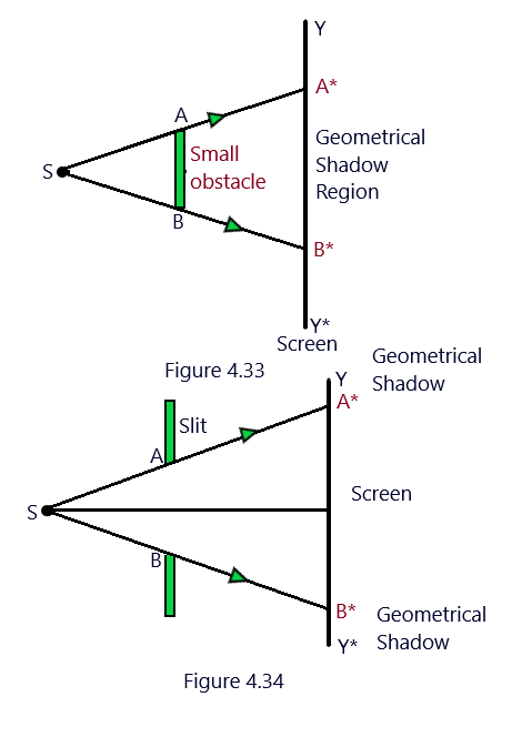
The casting of the shadows of the objects coming in its path is due to the nature of light that it travels in straight lines means due to rectilinear propagation of light. When a narrow slit is placed in the path of the light waves coming from a monochromatic source of light S as shown in the figure 4.34. (Diffraction of light)
Only the part A*B* called the illumination region, should get the illumination while no light should be obtained in the regions A*Y and B*Y* on the screen as being the geometrical shadow regions. (Diffraction of light)
In second case, when the slit is replaced by an obstacle AB then the distinct geometrical shadow region A*B* is obtained on the screen. It so happens because of the reason that the size of the slit or the size of an obstacle is quite large. (Diffraction of light)
However, The light enters in the geometrical shadow region in both cases of the slit and an obstacle, when the size of the slit or the obstacle is quite small, showing that the light bends round the corners of the slit or the obstacle. (Diffraction of light)
Thus, the diffraction is defined as the phenomenon of bending of light round the corners of the small obstacles, slits, and the apertures and spreading into geometrical shadow region.
The necessary condition for diffraction to take place is that the size of the obstacle placed in the path of a light wave must be comparable to the wavelength of the light used. In principle, all the types of wave motion exhibit the phenomenon of diffraction. The diffraction of radio waves and the sound waves are more pronounced in our daily life.
Experimental demonstration of Diffraction
In order to demonstrate the phenomenon of diffraction experimentally, take two razor blades and hold them in such a way that their sharp edges form a quite narrow slit in between. Now keep this slit in front of the eye and close to the it. Look on the straight filament of an electric glass bulb through this slit made with the two razor blades as discussed above. We shall observe a diffraction pattern consisting of an alternate bright and dark bands after making a slight adjustment in the width of this slit. (Diffraction of light)
types of diffraction of light
Depending upon the position of the source of light, and the screen, the diffraction of light is of two types.
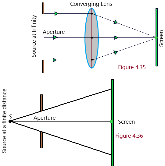
Fraunhoffer Type of Diffraction: The diffraction of light waves at a slit is said to be Fraunhoffer type of diffraction if a plane wavefront is incident on it and the emerging wavefront out of the slit is also a plane wavefront. This is possible when, either the source or the screen or both are placed at infinite distance from the lens as shown in [Figure 4.35]. (Diffraction of light)
While performing the experiment on the phenomenon of diffraction in laboratory, a convex lens is used between the source and the slit in order to make a plane wavefront incident on the slit. Again a convex lens is used between slit and the screen to bring the emergent wavefront on the screen. Diffraction at a single slit. Diffraction at the double slit, and diffraction at diffraction grating are the examples of Fraunhoffer Type of Diffraction. (Diffraction of light)
Fresnel Type of Diffraction: The diffraction of light waves at a slit is said to be Fresnel type of diffraction, when, either the source or the screen or both are placed at finite distance from the slit or obstacle as shown in [Figure 4.36] The wavefront is either spherical or cylindrical in nature as the source of light is close to the slit. Diffraction at straight edge and the diffraction at thin wire are the examples of Fresnel type of diffraction
Diffraction of light at a single slit
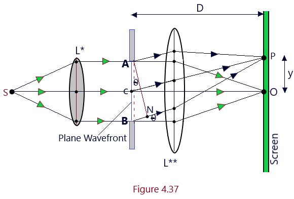
Let us suppose that a monochromatic source of light waves S is placed at the principal focus of the convex lens L* and is emitting the light waves of wavelength lemda. A parallel wavefront is so allowed to expose a narrow slit AB of width a The diffraction pattern will be obtained on the screen at a distance D from the slit in the focal plane of lens L**. The diffraction pattern so obtained consists of a central maxima corresponding to point O on the screen and a number of bright and dark fringes called secondary maxima and minima on either side of the central maxima.
On the basis of the data collected experimentally about the diffraction of light due to a single slit, following two inferences can be drawn-(1) The width of the central maxima (Principal Maxima) is twice the width of the secondary maxima. (2) The intensity of secondary maxima goes on decreasing as their order increases.
Central Maxima (Principal Maxima): When a parallel wavefront is exposed on the slit AB of width a then as per Huygen’s Principle, each point on this primary parallel wavefront act as a fresh source of secondary wavelets and thus, it becomes the source of secondary wavelength. These secondary wavelets spread out in all possible directions, however, these secondary wavelets are initially in phase. C is the mid point of slit AB and the secondary wavelets reaching the lens L** in a direction parallel to CO, the principal axis of the lens will meet at the point O on the screen in same phase as their optical paths are same between the slit and and the point O.

Positions and Widths of secondary maxima and minima: As is clear from Figure 4.37, the secondary wavelets are emitted in all the directions from each point on the plane primary wavefront AB. The secondary wavelets diffracted at an angle theta with the principal axis are converged at point P on the screen. (Diffraction of light)
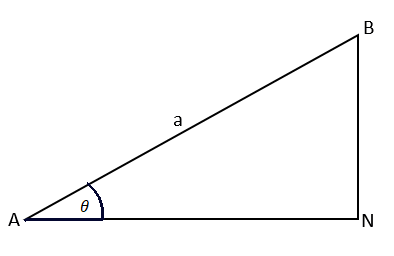
The secondary wavelets emitted from the different parts of the slit are in same phase but they do not reach the point P on the screen in same phase because they have to cover different distances in reaching the point P. The path difference between the secondary wavelets emitted from the extreme points of the slit AB) will be equal to BN, given by using the triangle ABN. (Diffraction of light)

Positions of Secondary Minima: There will be a secondary minima at any point on the screen, if the path difference between the secondary waves reaching that point is integral multiple of the wavelength, thus, for nth secondary minima, (Diffraction of light)

By putting the different integral values of n = 1, 2, 3,- – – we get the different positions of the secondary minima obtained on the screen. Thus,

Positions of different secondary Maxima: At any point on screen, there will be a secondary maxima, if the path difference between the secondary waves reaching that point is odd integral multiple of the half of their wavelength, thus, for nth secondary maxima, we can write,

By putting the different integral values of n = 1, 2, 3,- – – in Eqn. (B), we get the different positions of the secondary maxima obtained on the screen. Thus,
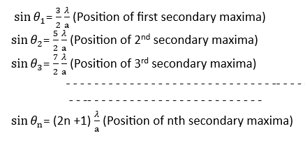
As an inference, it is to be noted that the diffraction pattern due to a single slit consists of principal or a central maxima at point O of the center of the screen surrounded by secondary minima and maxima alternately on either side of the central maxima. (Diffraction of light)
Intensity Distribution Graph/Curve: As discussed above, the central/principal maxima corresponds to the point O on the screen which is the central point of the exposed part of the screen and is followed by secondary minima and maxima alternately on both side of the central maxima. The intensity of the secondary maxima relating to the intensity of the central maxima are in the ratio as here 1 : (1/21) : (1/61) : (1/121) – – – – – – Thus, the intensity of first secondary maxima is just about 4% of that of the central maxima. (Diffraction of light)
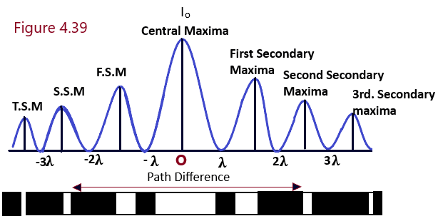
Intensity variations of secondary Maxima with its order: It has been clear that the intensity of the central maximum in the case of the diffraction through the single slit is due to the constructive interference of the secondary waves coming from all parts of the slit exposed to the light. The first secondary maximum is obtained due to the the contribution of the secondary waves from (1/3) part of the slit and the second secondary maximum is obtained due to the the contribution of the secondary waves from (1/5) part of the slit only and so on. Hence, when the order n of the maximum goes on increasing, the intensity of the secondary maxima decreases accordingly. (Diffraction of light)
Widths of central and secondary maxima :
Angular width of central maximum: Angular width of central maximum is defined as the angular separation or the angle between the directions of first secondary minima on two sides of the central maximum.

As shown in [Figure 4.40], the directions of each secondary minima on either side of the central maximum is represented by

Linear width of central maxima: Consider that distance of the screen from the center of the slit is D, then the linear distance of first minima from the center O of the screen can be written as

As the width of central maxima or principal maxima is equal to the linear distance between the first minima on either sides of the principal maximum and will be written as

Linear width of secondary maximum: The angular width of nth secondary maximum is defined as angular separation between the directions of nth and (n + 1)the minima.
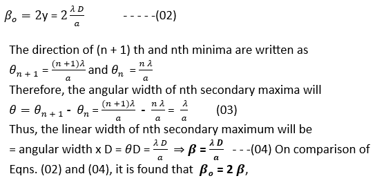
This implies that the width of central maxima is twice the width of secondary maxima and the width of the secondary maxima is inversely proportional to the width of the slit. Therefore, the secondary maxima get narrower as the slit width is increased. The secondary maxima of diffraction pattern completely disappears when the slit is of sufficiently large sized and the central maximum is only obtained which is the sharp image of the slit. It to conclude that a distinct diffraction pattern is obtained only when the narrow slit is used.
Comparison between interference and diffraction
Both of the phenomenon, the interference and the diffraction are the result of the superposition of the waves and hence, are not easily distinguishable from each other. When there are a number of sources of light sending the waves, then the resultant effect of the superposition of the waves from these sources is called the diffraction of light waves. But on the other side, when there are two independent coherent source of light, the superposition of the light waves emitted from the coherent waves is called the interference of light.
Difference between the interference and the diffraction
Interference
- It is the resultant effect of the superposition of the two coherent waves coming from the two independent coherent sources of light beams.
- All the bight and dark fringes in interference are of equal width.
- All the bight fringes, in interference pattern are of equal intensity.
- The regions of dark fringes are perfectly dark in interference, which leads to a good contrast between the bright and dark fringes.
- In interference pattern, large number of fringes/bands are observed on the screen.
- In the interference of light, a bright fringe is obtained in the interference pattern of two narrow slits separated by a distance d.
Diffraction
- It is the resultant effect of the superposition of the two secondary wavelets coming from the different points of the same wavefront.
- In diffraction, the width of central bright fringe is twice the width of other secondary maxima.
- In the Diffraction of light, intensity of the bright fringes decreases with the order of maxima. It means that the intensity of the bright fringes decreases as we go away from the central bright fringe on either sides.
- The region of dark fringes, in the pattern of diffraction of light, are not perfectly dark that gives rise to weak contrast between the dark and bright fringes.
- In the pattern of diffraction of light, small number of fringes/bands are observed on the screen.
- In the pattern of diffraction of light, first dark fringe is obtained at an angle of (t/a) due to a single slit.
Fresnel Distance:
Fresnel Distance is defined as the distance of the screen from the slit such that the spreading of light due to the diffraction from the center of the screen is just equal to the size of the slit. It is denoted by ZF.
As is well established fact that the diffraction pattern due to a single slit consists of secondary maxima and minima on both sides of the central maximum and therefore, on diffraction due to a slit, the light spreads out on the screen in the form of a central maximum. The half angular width of the central maximum is the the angular position of first secondary minimum is given by

When the screen is placed at least distance of distinct vision (D) from the slit, then the linear spread of the central maximum will be

In actual, the above Eqn. indicates that it is the distance of first secondary minimum from the center of the screen. It is also clear that the linear size of the central maximum implying that the spread of light on the screen goes on increasing as the screen is moved away (D is increased). Now from the definition of Fresnel distance, When, D=ZF, => y1=a, under this condition, the above Eqn. can take the form,

It is evident that the spreading of light due to diffraction of light, will be quite large as compared to the size of the slit when the screen is placed at a distance beyond the Fresnel Distance ZF.
Knowledge Points:
*The Diffraction of light is observed when the size of the obstacle is of the order of the wave length of light used.
*All the secondary maxima and minima, in the diffraction pattern due to a single slit are of the equal width and the width of the central maxima is twice as compared to that of any other secondary maxima or minima.
*The intensity of secondary maxima goes on decreasing as the order of the maximum increases in the case of diffraction pattern produced by a single slit.
*The intensity of central maxima does not depend on the width of the slit. However, the slit width has a direct impact on the width of the central maxima. The wider the slit is, the narrower is the central diffraction maximum.
*The two objects are said to be just resolved if the between the central maxima of their diffraction patterns is just equal to the distance between the central maximum and first secondary minimum of any of the two objects.
*The phenomenon of diffraction limits the resolving power of an optical instrument.
*The resolving power of a microscope or a telescope increases, when light of smaller wavelength is used.
