
This is an electric circuit in which a source of alternating emf is connected across a series combination of an induction coil of inductance L, a resistor of resistance R and a capacitor of capacitance C
Suppose that, the instantaneous values of emf and current in the LCR Circuit be E and I, so that the instantaneous values of the potential drop across the inductor, capacitor and resistor be VL , VC , and VR . Then applying Ohm’s Law, we can write, VL = I XL = I. wL L: VC= I. XC = I /wc.
: VR = I R; here, XL and, XC are the inductive and capacitive reactance’s.


Let us suppose that an alternating current passing through the LCR circuit along the X-axis as shown in Phasor diagram is shown as I =Iₒ Sin wt. —————-01
As shown in the phasor diagram, it is clear that
- The alternating current I at any time t is in phase with VR in an AC circuit containing resistance R only, so both are represented along OX.
- The alternating current I at any time, lags behind VL by a phase angle pi/2, so the VL is represented along OY
- The alternating current I at any time, leads ahead VC by a phase angle pi/2, so the VC is represented along OY’
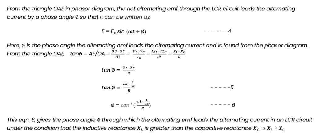
Consider that OA, OB and OC represent the magnitudes of the phasors VR VL and VC Thus the magnitude of the resultant emf across the LCR circuit will be OE in the phasor diagram. Thus

What is the Impedance of LCR Circuit?
The impedance of a series LCR circuit (Z) is the total effective resistance provided to the alternating current by an electric circuit containing an induction coil of inductance L, a capacitor of capacitance C, and a resistor of resistance R connected in series is given by equation 6, as

It is evident from eqn. 7 that the impedance of the LCR series circuit in addition to the elements, L, C, and R depends strongly on the angular frequency (w) of the alternating source because the inductive and the capacitive reactance’s (wL and 1/wC) change with the change in angular frequency of the signal source. The inductive reactance wL is low at lower angular frequency (w) but the capacitive reactance (1/wC) is high. Therefore, with the increase in the angular frequency, the inductive reactance (wL) increases but the capacitive reactance (1/wC) decreases. At a particular angular frequency (w0) of the source of alternating emf, the inductive reactance becomes equal to the capacitive reactance, therefore,

Form the eqn. 8, we see that the impedance of the LCR circuit (z) is minimum corresponding to the angular frequency w0 and consequently maximum current flows through the circuit. This stage of the LCR circuit is called as electric resonance and the corresponding angular frequency is called as resonant frequency. The instantaneous value of alternating current passing through the LCR circuit at resonance will be I = E/R
Definition of Resonance
The resonance is an electric stage of an LCR series circuit when its total impedance becomes minimum and the maximum alternating current flows through it and the corresponding frequency is called as resonant frequency.
Characteristics of resonance


power factor is maximum in a series LCR circuit when
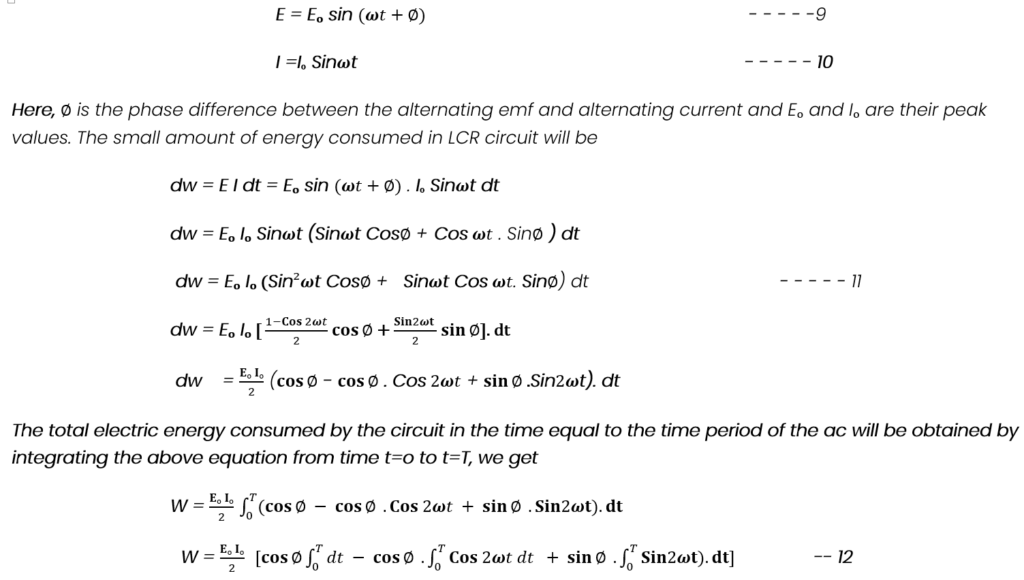
The instantaneous power of an electric a.c. circuit is defined as the product of the instantaneous emf and the instantaneous value of current passing through the circuit. Let us suppose that the instantaneous emf and current in an LCR circuit are given by

The average power or the true power of an LCR circuit strongly depends upon the power factor and is maximum when the power factor is maximum, which is possible when the ac circuit is purely resistive. Therefore, when an ac circuit contains resistance only, its power is maximum. When an inductor or a capacitor or both are connected in series with the resistor, the power of the ac circuit decreases always.
Quality factor of lCR circuit
Quality Factor is also called as Q-factor of an LCR circuit and is defined as the ratio of the voltage drop across the inductor or the capacitor to the voltage applied to the LCR circuit. Thus,

If I is the instantaneous value of current flowing through the LCR circuit when electric resonance taken place, the voltage drop across the inductance L will be I XL and the voltage applied across the circuit is given by I R, so that the we can write the above equation of quality factor as


Conclusions of Quality Factor
- The Q -factor of the LCR circuit gives the sharpness or the selectiveness of the electric resonance.
- The Q -factor of the LCR circuit will be large having more selectivity and more sharpness for smaller values of resistances or L is large and C is low
Parallel LC- Circuit
Suppose that a source of an alternating emf is connected with a parallel combination of an induction coil of inductance L and a capacitor of capacitance C such that the instantaneous value of alternating emf is given by
E = Eₒ Sin wt – – – – – 16
If I be the alternating current in this circuit at that moment and IL and IC be the instantaneous currents through the inductor and capacitor, then we can write
I=IL +IC – – – – – 17
As we know that the alternating current through the inductor lags behind the alternating emf by a phase difference of pi/2, and alternating current through the capacitor leads the alternating emf by a phase difference of pi/2. Therefore, we can write


Parallel Resonance Circuit
The impedance of the LC-Parallel circuit is given by the expression Z= 1/ ( wC -1/wL).


Energy Stored in a capacitor and an Inductor in LCR Circuit
Energy Stored in a capacitor
When a capacitor is connected to the source of emf, the energy is stored within the electric field of the capacitor as given by
U = q2 /2C = CV2 /2 = qV/2 —23
Features of energy Stored in a capacitor
- The energy stored within the capacitor is at the cost of the energy of the source of emf.
- The energy resides with in the capacitor in the form of electric field.
- In case when the source is of an alternating emf. the energy is stored within the capacitor during one half cycle of the alternating current while during the next half cycle, the same amount of energy is returned back to the source. It is due to this reason that the average electric power of of a capacitor is zero over a complete cycle of ac.
Energy Stored in an Inductor
when an inductor is connected to the source of emf, the energy is stored within its magnetic field of the inductor which is given by
U=(1/2)L I2 —24
Features of energy Stored in an inductor
- The energy stored within the inductor is at the cost of the energy of the source of emf.
- The energy resides with in the capacitor in the form of electric field.
- In case when the source is of an alternating emf. the energy is stored within the inductor during one half cycle of the alternating current while during the next half cycle, the same amount of energy is returned back to the source. It is due to this reason that the average electric power of of an inductor is zero over a complete cycle of ac
Summary
- The reciprocal of Impedance of an LCR circuit is called admittance.
- When resonance takes place in LCR circuit, wL = 1/wC; The impedance is minimum and equal to R, I and E are in same phase and current in the circuit is maximum.
- Energy stored in a capacitor resides inside it in the form of Electric Field.
- Energy stored in an inductor resides inside it in the form of magnetic Field.