images formed by lenses
The images formed by lenses-12 when the two or more light rays from different parts of an object after refraction through the lenses actually converge at a point or appear to do so.
image formed by a convex lens
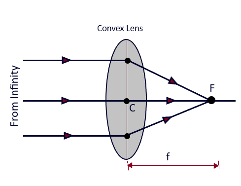
(A) when the object lies at infinity: (Images formed by Lenses-12)
Let us suppose that the object is placed at infinity as shown in the Fig. 3.12. The lens equation -1/u + 1/v = 1/f, in this case when the object is situated at infinity will take the form, (Images formed by Lenses-12)

The image will be real and formed on the other side of the convex lens as the focal length of the convex lens is positive, so v will also be positive. The magnification in this case will be, m = v/u =v /infinity =0,
Therefore, when an object lies at infinity, the image will be formed at the principal focus F, and it will be real, inverted and point sized image irrespective, the object is linear one. (Images formed by Lenses-12)

(B) When the object lies beyond 2F:
Let us suppose that the object is placed on the principal axis of a convex lens at a distance greater than 2F beyond 2F) as shown in the Fig. 3.1, so that the distance of the object AB from the, optical center of the is negative is greater than 2f. Now from the lens equation,

Then it follows that, the image distance, v will be positive and its value will lie between f and 2f so the image will be formed between f and 2f on the other side of the lens. (Images formed by Lenses-12)

(C) When the object lies at 2F
Let us suppose that an object AB is placed on the principal axis of a convex lens at a distance 2F from it optical center as shown in the Fig. 3.13 so that the distance of the object AB from the, optical center of the is negative and equal to 2f. Now from the lens equation, (Images formed by Lenses-12)

Thus, from this we draw a conclusion that, the image will be formed at 2F and will be real. Inverted and equal sized for an object placed at 2F. (Images formed by Lenses-12)

Let us suppose that an object AB is placed on the principal axis of a convex lens at a distance between f and 2f from its optical center as shown in the Fig. 3.15 so that the distance of the object AB from the, optical center of the is negative and lies between f and 2f. Now from the lens equation,
(D) When the object is placed between F and 2F
Let us suppose that an object AB is placed on the principal axis of a convex lens at a distance between f and 2f from its optical center as shown in the Fig. 3.15 so that the distance of the object AB from the, optical center of the is negative and lies between f and 2f. Now from the lens equation, (Images formed by Lenses-12)

Therefore, the real, inverted and large sized image will be formed beyond 2f, when the object is placed between F and 2F(Images formed by Lenses-12)

(E) When the object is placed at the Principal Focus F
Let us suppose that an object AB is placed on the principal axis of a convex lens at point F and at a distance f from its optical center as shown in the Fig. 3.16 so that the distance of the object AB from the, optical center of the is negative and is equal to f. Now from the lens equation,

Therefore, a real, inverted and highly magnified image is formed at infinity when an object is placed at the focal point.(Images formed by Lenses-12)

(F) When the object is placed between F and C
Let us suppose that an object AB is placed on the principal axis of a convex lens between F and C as shown in the Fig. 3.17 so that the distance of the object AB from the, optical center of the is negative and is less than f. Now from the lens equation, (Images formed by Lenses-12

Therefore, a virtual, erect, and magnified image is formed on the same side of the lens, for an object when placed on the principal axis between F and C. (Images formed by Lenses-12)

image formed by A concave lens

Let us suppose that an object AB is placed on the principal axis of a concave lens between F and C as shown in the Fig. 3.18. and an image A*B* if formed on the same side of the concave lens. From the ray diagram as shown here, that the object distance (u) and image distance (v) both are negative. From the lens equation, we have

Since, the object distance (u) and image distance (v) both are negative, it follows that v will be negative and v < f as the image is on the same side of the lens and between F and C. From m = v/u, it is clear that m will be positive and less than 1(virtual and smaller in size). It is very clear that irrespective of the position of the object, a concave lens always produces a virtual and erect image on the same side of the lens which is smaller in size. (Images formed by Lenses-12)
Power of a lens

As shown in fig. 3.19 above, we see that the lenses which converge or diverge the light rays more, their focal lengths are smaller and vice-versa.
The ability of a lens, to converge or to diverge the light rays, incident on it, is called the power of a lens and The is measured as the reciprocal of its focal length.
Thus, Power of the lens = 1/ focal length of the lens => P = 1/f (in meter).
Units of Measurement It is measured in diopter (D), therefore, P = 1/f. If f = 1 meter, then P = 1/f = 1/ 1m = 1 m-1 = 1 diopter (D) Thus, the power of a lens is said to be one diopter, when its focal length is one meter.(Images formed by Lenses-12)
The power of a convex lens/converging lens is taken to be positive while for concave/diverging lens, it is taken to be negative. The power of a lens is characteristic to its focal length in terms of image distance, nature of image and size of the image as it is just the reciprocal of the focal length of the lens. As per the Len’s maker’s formula,

Here, the radius of curvatures R1 and R2 are measured in meter and the power of lens P, is measured in diopter. (Images formed by Lenses-12)
Equivalent lens of the Combination of lenses
An equivalent lens of the combination of two on more lenses is a single lens, which will form the image of a given object at the same point as is formed by the component lenses together making a combination. (Images formed by Lenses-12)

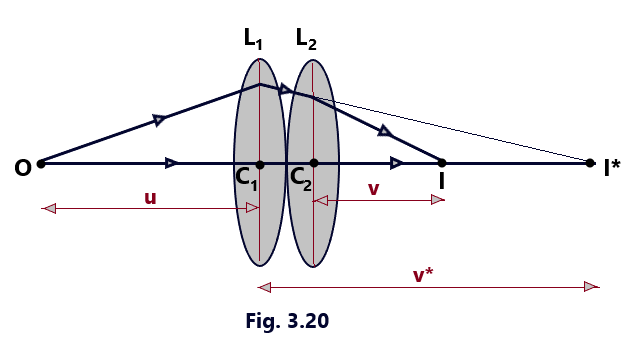
Let us consider that the two thin lenses L1 and L2 of focal lengths, f1 and f2 are placed in contact with each other. Suppose that a point object O lies on the principal axis of the two lenses, as in figure 3. 20. This figure shows the formation of the final image I of the object O in the two steps. In the first step, the lens L1 produces I* as the real image of the object O. If C1 O = u and &C1 I*= v*, then for lens L1 we have

In the second step, the final image I is produced by lens L2 . of the image I* made by L1 acting as the virtual object. As the two lenses taken in contact are supposed to be thin, implies that C2 I* = C1 I*= +v*. The positive sign with v* is taken because of the reason that the distance of image I* from C2 is measured in the direction of incident ray. If C2 I =v, then the focal length of the lens L2 is given by

Here, the eqn. 3.26 represents the focal length of the equivalent lens and shows that the reciprocal of the focal length of the equivalent lens is equal to the sum of the reciprocals of the focal length of the two lenses placed in contact. (Images formed by Lenses-12)
Conclusions
- When f1 and f2 are the focal lengths of the two lenses in contact (in meter), then the above eqn. (3.26) in terms of their powers is represented as P =P1 + P2 – – – – -(3. 27). In general P =P1 + P2 + p3 + P4 + Pn – – – – – (3.28) (Images formed by Lenses-12) Thus, when a number of thin lenses are placed in contact, then the power of the equivalent lens is equal to the sum of the powers of the individual lenses. (Images formed by Lenses-12)
- When two lenses are placed in contact then, the image produced by first lens acts as the object for the second lens, which further produces image of this image. If m1 and m2 are magnifications produced by the 1st and the 2nd lens, respectively, then, the total magnification produced by their combination is given by. m = m1 x m2 and in general, m =m1 + m2 + m3 + m4 + ———+ mn (Images formed by Lenses-12) Thus, when a number of thin lenses are placed in contact. The magnification produced by the combination is equal to the product of the magnification produced by the individual component lenses.(Images formed by Lenses-12)
- When the two lenses are not combined by placing them in contact with each other but are placed at a finite distance apart. It. It can be proved that if two lenses of focal lengths, f1 and f2 are placed at a distance X apart, then focal length of the equivalent length is given by 1/f = 1/ f1 + 1 / f2 – x / (f1 f2 ) – – – – – – (3.29) (Images formed by Lenses-12)
- The two lenses may be combined so as to produce magnified image, to produce erect image and to minimize the lens defects like chromatic aberrations or spherical aberrations. (Images formed by Lenses-12)
Spherical aberration in lenses
The inability of a lens of large aperture to bring all the rays in a wide beam to focus at a single point is called spherical aberration.


Cause of Spherical aberration
The light rays traveling parallel to the principal axis after refraction from a convex lens meet at a single point only if the beam of light is narrow or if the lens is of small aperture. In case, when a wide beam of light falls on the convex lens of large aperture, the rays after refraction through the lens, do not come to focus at a single point.
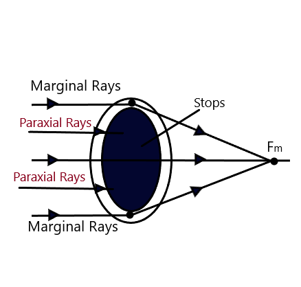
In the wide beam of light, the light rays which travel close to the principal axis, are called paraxial rays, while the rays which travel quite away from the principal axis are called marginal rays. It is found that the marginal rays get focused relatively close to the optical center of the lens, as compared to the paraxial rays. (Images formed by Lenses-12)
Figures, 3.20. and 3.22, show the focusing of the marginal and paraxial rays in case of the convex and concave lens respectively. It follows that the focus of marginal rays Fm is closer to the optical center than the focus for paraxial rays Fp. Therefore, a lens of large aperture is unable to bring a parallel beam of light to a sharp focus at a point on its principal axis. (Images formed by Lenses-12)
Thus, spherical aberration is a defect in a lens of wide aperture, due to its different focal lengths, for the light refracted from the different parts of the lens. It follows that the focal length of the lens for marginal rays fm is less than that for paraxial rays fp. The difference in the focal length for the paraxial rays and marginal rays provides us, the measure of the axial or the longitudinal spherical aberration. Thus, the longitudinal spherical aberration equal = fp – fm.
When the screen is moved between the focus points of the paraxial and marginal rays on the principal axis of the lens, then it is observed that the size of the image goes on varying and is minimum at a certain position between Fm and Fp. This circular image in this position is called as circle of least confusion and it gives the best position for the focus for the parallel beam of light. The variation in the size of the circular image is called lateral spherical aberration and the radius of this circle of least confusion is the measure of lateral spherical aberration. (Images formed by Lenses-12)
How to minimize Spherical Aberrations?
The spherical aberrations can successfully be minimized by adopting any one of the following methods.


- By using Stops: Stops are the thin layers of opaque material coated on the lenses and it allows either the marginal rays or the paraxial rays through the lenses as shown in the figures above. Spherical aberration in a lens of wide aperture can be minimized by using stops so as to either allow paraxial or marginal rays to fall on the lens. In this way, we can minimize the spherical aberration to greater degree of precession but in practical, it can not be reduced to zero. (Images formed by Lenses-12)
- By placing the lens so that the total deviation is shared equally by the two surfaces of the lens : We know that In case of a Plano – convex lens, the spherical aberration is minimum, when it’s curved surface faces, incident or emergent rays, whichever is more parallel to the principal axis. Thus, the spherical aberration can be precisely reduced when we use this method. (Images formed by Lenses-12)
- By using two Plano – Convex Lenses : The spherical aberration can be minimized to the satisfactory level when we use two Plano – convex lenses such that the distance between these two Plano – Convex lenses is equal to the difference of their focal lengths. If the focal lengths of the two Plano – Convex lens are f1 and f2 and x is the distance of separation between them, then x = f1 – f2
Key Points:
- The image produced by a concave lens is always virtual and smaller in size.
- The power of a thick lens is always greater than the power of a thin lens.
- The power of an equivalent lens is equal to the sum of the powers of the individual lenses when a number of lenses are placed in contact with each other.
- The magnification of an equivalent lens is equal to the product of the magnifications produced by the individual lenses when a number of lenses are placed in contact with each other.

8 Comments